Research Area
Sensorless Control of Electric Machines
1. Sensorless Control Algorithm
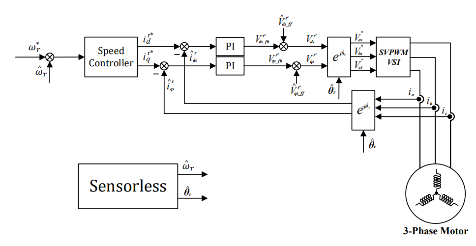
-
- • Sensorless control algorithm based back EMF
- • Sensorless control algorithm based saliency of rotor employing injecting high-frequency voltage
- • Robust sensorless control algorithm of induction motor to varying temperature
2. Open-loop Starting Algorithm at low speed

-
- • PMSM open-loop algorithm to ensure current control at low speed
3. Super High Speed Sensorless Control Algorithm
-
- • Super high speed sensorless in many applications such as home appliances, compressors, blowers
Inverter Topologies
1. Three-phase and single-phase motor drive system with single three-phase two-level inverter for independent speed control [1]

-
- • The single-phase motor is connected in series between the neutral point of the three-phase motor and the mid point of two split DC-link capacitors
- • Two motors can be controlled independently using single three-phase two-level inverter
- • The proposed drive system can reduce the number of power switches compared with the conventional drive system that uses a single-phase and a three-phase inverter
References
[1] Park, DH., Kim, M. & Lee, WJ. Three-phase and single-phase motor drive system with single three-phase two-level inverter for independent speed control. J. Power Electron. 22, 40–49 (2022).
Efficiency Analysis of Motor Drive Systems
1. Inverter efficiency analysis simulation
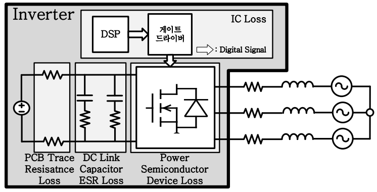
[Inverter loss equivalent circuit]
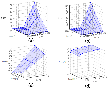
[Inverter loss model: (a) Turn on loss. (b) Turn off loss. (c) Rds(on). (d) Diode Forward Voltage.]
- • Inverter conduction loss and switching loss analysis by PWM
- • Inverter efficiency analysis according to dead time
2. Analysis of overall efficiency of electric motor drive system
-
- • Simulate overall efficiency with the sum of inverter loss by PWM method and switching frequency, and motor loss such as copper loss and iron loss
- • Comparison of actual measured losses and simulation-predicted losses
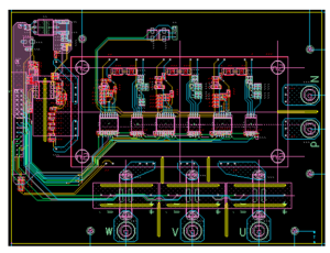
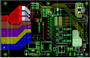
Power Electronics H/W Design
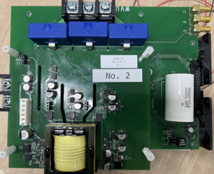
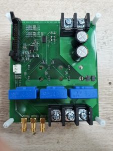
1. Inverter
-
- • 10kW general purpose 1200V/100A Infineon IGBT Module
- • 1200V/100A IGBT Module Inverter for driving 11kW 100,000RPM Turbo-blower
- • 600V/30A IPM Module Inverter for driving 2kW 67,000RPM Turbo-blower
- • 6kW 1200V/50A IGBT Module Inverter
- • 8kW 1200V/100A SiC Module Inverter
- • 250W 40V/50A MOSFET Module Inverter
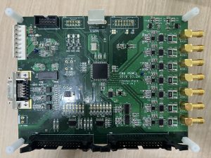
2. Controller
-
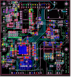
- • MCU Control Board for driving Motor
Single Phase PMSM
1. Maximum Torque Capability Analysis [1]
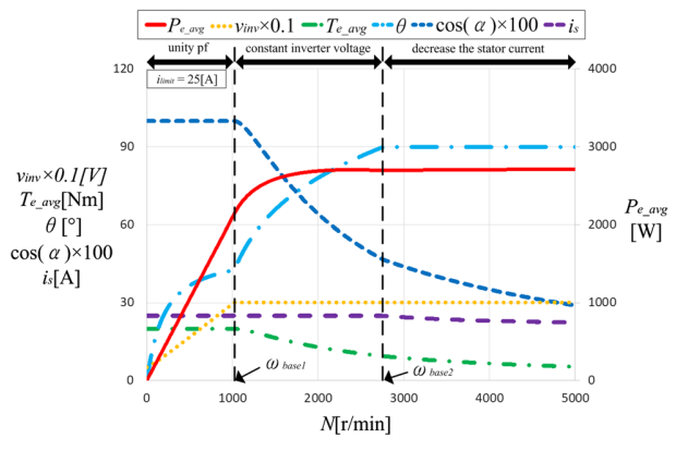
[SP-PMSM capability curve at ke < Ls*I_limit & ke > Ls*I_limit]
- • The proposed method requires only motor parameters and limited voltage and current conditions
- • The inverter output voltage that minimizes the copper loss is given easily by the combination of capability curve information
2. Variable Speed Control Method [2]
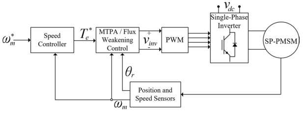
[Proposed the inverter output voltage control of SP-PMSM]
- • All speed and given load torque under the maximum torque capability curve of the SP-PMSM can be controlled to MTPA operation without a current controller
- • Control scheme is simple and easy, and has the fast calculation time to implement compared to any other control schemes.
3. Sensorless Vector Control [3]
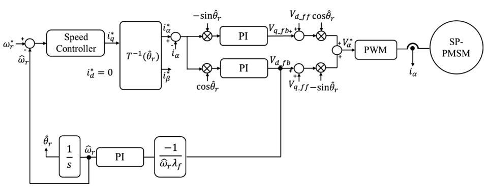
[The block diagram of the sensorless vector control scheme for single-phase PMSM]
- • This proposed method does not need any process to generate the orthogonal virtual current component which is generally used to control the current in synchronous reference frame
- • The sensorless control scheme can be easily implemented without modification of hardware
References
[1] Choi, S., Lee, WJ. Maximum Torque per Ampere Control of a Single-Phase Permanent Magnet Synchronous Motor, Part 1: Maximum Torque Capability Analysis. J. Electr. Eng. Technol. 15, 2617–2625 (2020).
[2] Choi, S., Lee, WJ. Maximum Torque Per Ampere Control of a Single-Phase Permanent Magnet Synchronous Motor, Part 2: Variable Speed Control Method. J. Electr. Eng. Technol. 15, 2609–2616 (2020).
[3] Jo, SI., Lee, WJ. A Sensor-Less Vector Control for Single-Phase Permanent Magnet Synchronous Motor. J. Electr. Eng. Technol. (2023).
Compensation method
1. Compensation method of average current sampling error under the operation condition of low sampling to fundamental frequency ratio [1]

[Simulation result with the proposed method] [The d,q average current during one sampling period]
- • When the sampling to fundamental frequency ratio is lowered, the current ripple is very large, and an error between the sampled current and the average current during one sampling period occurs
- • The proposed compensation method of average current sampling error can be implemented based on the reference voltage and sampled current
2. Compensation method of PWM inverter output voltage under the operation condition of low sampling to fundamental frequency ratio [2]

[Trajectory of the voltage vectors in the synchronous reference frame at a low Fratio, Proposed control block diagram]
- • Output voltage errors of a PWM inverter occur under low sampling to fundamental frequency ratio operating condition
- • Output voltage errors can be compensated by calculating a switching timing in which the average of the output voltage during one sampling period is equal to the voltage reference
3. Compensation method of current measurement errors due to sensor scale error and non-simultaneous sampling error for 3 phase inverter [3]

[PWM carrier and over-sampling points: a case1; b case 2; c case 3]
- • The scaling error can be compensated offline simply by turning off one phase of the inverter
- • The error compensation methods for the non-simultaneous sampling error are proposed according to the number of sample and hold(S/H) circuits in the current sensor and analog-to-digital converters(ADCs)
Estimation method
1. Inverter average input power estimation under the operation condition of low sampling to fundamental frequency ratio [4]
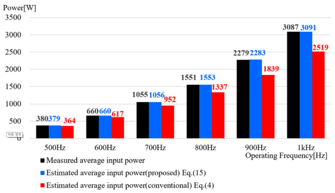
[Comparison the average input powers of the proposed and conventional method(simulation)
- • When the current sampling frequency to operating frequency is low, the error between the sampled phase current and the average phase current is large. This results in an error of the inverter average input power estimation
- • In this paper, the average currents are calculated for every voltage vector duration within a current sampling period. The average phase currents are multiplied by the phase voltages to estimate the inverter average input power
References
[1] Jo, SI., Lee, WJ. Compensation method of average current sampling error under the operating condition of low sampling-to-fundamental frequency ratio. J. Power Electron. 23, 649–655 (2023).
[2] Jo, SI., Lee, WJ. Compensation method of PWM inverter output voltage under low sampling-to-fundamental frequency ratio operating conditions. J. Power Electron. 23, 904–912 (2023).
[3] Kim, MS., Park, DH. & Lee, WJ. Compensation of current measurement errors due to sensor scale error and non-simultaneous sampling error for three-phase inverter applications. J. Power Electron. 22, 31–39 (2022).
[4] Kim, M., Lee, WJ. Inverter average input power estimation algorithm in low-frequency modulation index operation of permanent magnet synchronous motors. J. Power Electron. 23, 274–283 (2023).
